The TCP "connection" is not an end-to-end TDM or FDM circuit as in a circuit-switched network. Nor is it a virtual circuit (see Chapter 1), as the connection state resides entirely in the two end systems. Because the TCP protocol runs only in the end systems and not in the intermediate network elements (routers and bridges), the intermediate network elements do not maintain TCP connection state. In fact, the intermediate routers are completely oblivious to TCP connections; they see datagrams, not connections.
A TCP connection provides for full duplex data transfer. That is, application-level data can be transferred in both directions between two hosts - if there is a TCP connection between process A on one host and process B on another host, then application-level data can flow from A to B at the same time as application-level data flows from B to A. TCP connection is also always point-to-point, i.e., between a single sender and a single receiver. So called "multicasting" (see Section 4.8) -- the transfer of data from one sender to many receivers in a single send operation -- is not possible with TCP. With TCP, two hosts are company and three are a crowd!
Let us now take a look at how a TCP connection is established. Suppose a process running in one host wants to initiate a connection with another process in another host. Recall that the host that is initiating the connection is called the client host, while the other host is called the server host. The client application process first informs the client TCP that it wants to establish a connection to a process in the server. Recall from Section 2.6, a Java client program does this by issuing the command:
Once a TCP connection is established, the two application processes can send data to each other; because TCP is full-duplex they can send data at the same time. Let us consider the sending of data from the client process to the server process. The client process passes a stream of data through the socket (the door of the process), as described in Section 2.6. Once the data passes through the door, the data is now in the hands of TCP running in the client. As shown in the Figure 3.5-1, TCP directs this data to the connection's send buffer, which is one of the buffers that is set aside during the initial three-way handshake. From time to time, TCP will "grab" chunks of data from the send buffer. The maximum amount of data that can be grabbed and placed in a segment is limited by the Maximum Segment Size (MSS). The MSS depends on the TCP implementation (determined by the operating system) and can often be configured; common values are 1,500 bytes, 536 bytes and 512 bytes. (These segment sizes are often chosen in order to avoid IP fragmentation, which will be discussed in the next chapter.) Note that the MSS is the maximum amount of application-level data in the segment, not the maximum size of the TCP segment including headers. (This terminology is confusing, but we have to live with it, as it is well entrenched.)
TCP encapsulates each chunk of client data with TCP header, thereby forming TCP segments. The segments are passed down to the network layer, where they are separately encapsulated within network-layer IP datagrams. The IP datagrams are then sent into the network. When TCP receives a segment at the other end, the segment's data is placed in the TCP connection's receive buffer. The application reads the stream of data from this buffer. Each side of the connection has its own send buffer and its own receive buffer. The send and receive buffers for data flowing in one direction are shown in Figure 3.5-1.
We see from this discussion that a TCP connection
consists of buffers, variables and a socket connection to a process in
one host, and another set of buffers, variables and a socket connection
to a process in another host. As mentioned earlier, no buffers or variables
are allocated to the connection in the network elements (routers,
bridges and repeaters) between the hosts.
Figure 3.3-2 shows the structure of the TCP segment. As with UDP, the header includes source and destination port numbers, that are used for multiplexing/demultiplexing data from/to upper layer applications. Also as with UDP, the header includes a checksum field. A TCP segment header also contains the following fields:

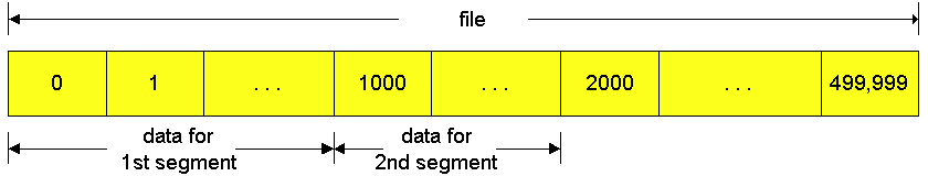
TCP views data as an unstructured, but ordered, stream of bytes. TCP's use of sequence numbers reflects this view in that sequence numbers are over the stream of transmitted bytes and not over the series of transmitted segments. The sequence number for a segment is the byte-stream number of the first byte in the segment. Let's look at an example. Suppose that a process in host A wants to send a stream of data to a process in host B over a TCP connection. The TCP in host A will implicitly number each byte in the data stream. Suppose that the data stream consists of a file consisting of 500,000 bytes, that the MSS is 1,000 bytes, and that the first byte of the data stream is numbered zero. As shown in Figure 3.5-3, TCP constructs 500 segments out of the data stream. The first segment gets assigned sequence number 0, the second segment gets assigned sequence number 1000, the third segment gets assigned sequence number 2000, and so on.. Each sequence number is inserted in the sequence number field in the header of the appropriate TCP segment.
Now let us consider acknowledgment numbers. These are a little trickier than sequence numbers. Recall that TCP is full duplex, so that host A may be receiving data from host B while it sends data to host B (as part of the same TCP connection). Each of the segments that arrive from host B have a sequence number for the data flowing from B to A. The acknowledgment number that host A puts in its segment is sequence number of the next byte host A is expecting from host B. It is good to look at a few examples to understand what is going on here. Suppose that host A has received all bytes numbered 0 through 535 from B and suppose that it is about to send a segment to host B. In other words, host A is waiting for byte 536 and all the subsequent bytes in host B's data stream. So host A puts 536 in the acknowledgment number field of the segment it sends to B.
As another example, suppose that host A has received one segment from host B containing bytes 0 through 535 and another segment containing bytes 900 through 1,000. For some reason host A has not yet received bytes 536 through 899. In this example, host A is still waiting for byte 536 (and beyond) in order to recreate B's data stream. Thus, A's next segment to B will contain 536 in the acknowledgment number field. Because TCP only acknowledges bytes up to the first missing byte in the stream, TCP is said to provide cumulative acknowledgements.
This last example also brings up an important but subtle issue. Host A received the third segment (bytes 900 through 1,000) before receiving the second segment (bytes 536 through 899). Thus, the third segment arrived out of order. The subtle issue is: What does a host do when it receives out of order segments in a TCP connection? Interestingly, the TCP RFCs do not impose any rules here, and leave the decision up to the people programming a TCP implementation. There are basically two choices: either (i) the receiver immediately discards out-of-order bytes; or (ii) the receiver keeps the out-of-order bytes and waits for the missing bytes to fill in the gaps. Clearly, the latter choice is more efficient in terms of network bandwidth, whereas the former choice significantly simplifies the TCP code. Throughout the remainder of this introductory discussion of TCP, we focus on the former implementation, that is, we assume that the TCP receiver discards out-of-order segments.
In Figure 3.5.3 we assumed that the initial sequence number was zero.
In truth, both sides of a TCP connection randomly choose an initial sequence
number. This is done to minimize the possibility a segment that is still
present in the network from an earlier, already-terminated connection
between two hosts is mistaken for a valid segment in a later connection
between these same two hosts (who also happen to be using the same port
numbers as the old connection) [Sunshine 78].
Suppose one host, 88.88.88.88, initiates a Telnet session with host 99.99.99.99. (Anticipating our discussion on IP addressing in the next chapter, we take the liberty to use IP addresses to identify the hosts.) Because host 88.88.88.88 initiates the session, it is labeled the client and host 99.99.99.99 is labeled the server. Each character typed by the user (at the client) will be sent to the remote host; the remote host will send back a copy of each character, which will be displayed on the Telnet user's screen. This "echo back" is used to ensure that characters seen by the Telnet user have already been received and processed at the remote site. Each character thus traverses the network twice between when the user hits the key and when the character is displayed on the user's monitor.
Now suppose the user types a single letter, 'C', and then grabs a coffee. Let's examine the TCP segments that are sent between the client and server. As shown in Figure 3.5-4, we suppose the starting sequence numbers are 42 and 79 for the client and server, respectively. Recall that the sequence number of a segment is the sequence number of first byte in the data field. Thus the first segment sent from the client will have sequence number 42; the first segment sent from the server will have sequence number 79. Recall that the acknowledgment number is the sequence number of the next byte of data that the host is waiting for. After the TCP connection is established but before any data is sent, the client is waiting for byte 79 and the server is waiting for byte 42.
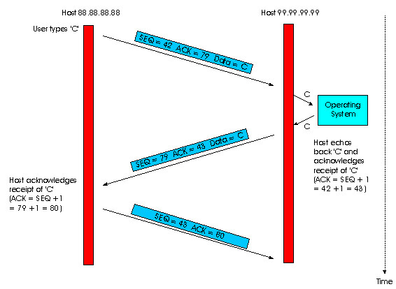
As shown in Figure 3.5-4, three segments are sent. The first segment is sent from the client to the server, containing the one-byte ASCII representation of the letter 'C' in its data field. This first segment also has 42 in its sequence number field, as we just described. Also, because the client has not yet received any data from the server, this first segment will have 79 in its acknowledgment number field.
The second segment is sent from the server to the client. It serves a dual purpose. First it provides an acknowledgment for the data the client has received. By putting 43 in the acknowledgment field, the server is telling the client that it has successfully received everything up through byte 42 and is now waiting for bytes 43 onward. The second purpose of this segment is to echo back the letter 'C'. Thus, the second segment has the ASCII representation of 'C' in its data field. This second segment has the sequence number 79, the initial sequence number of the server-to-client data flow of this TCP connection, as this is the very first byte of data that the server is sending. Note that the acknowledgement for client-to-server data is carried in a segment carrying server-to-client data; this acknowledgement is said to be piggybacked on the server-to-client data segment.
The third segment is sent from the client to the server. Its sole purpose is to acknowledge the data it has received from the server. (Recall that the second segment contained data -- the letter 'C' -- from the server to the client.) This segment has an empty data field (i.e., the acknowledgment is not being piggybacked with any cient-to-server data). The segment has 80 in the acknowledgment number field because the client has received the stream of bytes up through byte sequence number 79 and it is now waiting for bytes 80 onward. You might think it odd that this segment also has a sequence number since the segment contains no data. But because TCP has a sequence number field, the segment needs to have some sequence number.
TCP creates a reliable data transfer service
on top of IP's unreliable best-effort service. Many popular application
protocols -- including FTP, SMTP, NNTP, HTTP and Telnet -- use TCP rather
than UDP primarily because TCP provides reliable data transfer service.
TCP's reliable data transfer service ensures that the data stream that
a process reads out of its TCP receive buffer is uncorrupted, without gaps,
without duplication, and in sequence, i.e., the byte stream is exactly
the same byte stream that was sent by the end system on the other side
of the connection. In this subsection we provide an informal overview
of how TCP provides reliable data transfer. We shall see that the reliable
data transfer service of TCP uses many of the principles that we studied
in Section 3.4.
Retransmissions
Retransmission of lost and corrupted data is crucial for providing reliable data transfer. TCP provides reliable data transfer by using positive acknowledgments and timers in much the same way as we studied in section 3.4. TCP acknowledges data that has been received correctly, and retransmits segments when segments or their corresponding acknowledgements are thought to be lost or corrupted. Just as in the case of our reliable data transfer protocol, rdt3.0, TCP can not itself tell for certain if a segment, or its ACK, is lost, corrupted, or overly delayed. In all cases, TCP's response will be the same: retransmit the segment in question.
TCP also uses pipelining, allowing the sender to have multiple transmitted but yet-to-be-acknowledged segments outstanding at any given time. We saw in the previous section that pipelining can greatly improve the throughput of a TCP connection when the ratio of the segment size to round trip delay is small. The specific number of outstanding unacknowledged segments that a sender can have is determined by TCP's flow control and congestion control mechanisms. TCP flow control is discussed at the end of this section; TCP congestion control is discussed in Section 3.7. For the time being, we must simply be aware that the sender can have multiple transmitted, but unacknowledged, segments at any given time.
sendbase = initial_sequence number /*
see Figure 3.4-11 */
nextseqnum = initial_sequence number
loop (forever) {
switch(event)
event:data received from
application above
create TCP segment with sequence number nextseqnum
start timer for segment nextseqnum
pass segment to IP
nextseqnum
= nextseqnum + length(data)
event: timer timeout for
segment with sequence number y
retransmit segment with sequence number y
compue new timeout interval for segment y
restart timer for sequence number y
event: ACK received,
with ACK field value of y
if (y > sendbase) { /* cumulative ACK of all data up to y */
cancel all timers for segments with sequence numbers < y
sendbase = y
}
else { /* a duplicate ACK for already ACKed segment */
increment number of duplicate ACKs received for y
if (number of duplicate ACKS received for y == 3) {
/* TCP fast retransmit */
resend segment with sequence number y
restart timer for segment y
}
} /* end of loop forever */
Figure 3.5-5 shows the three major events related to data transmission/retransmission at a simplified TCP sender. Let us consider a TCP connection between host A and B and focus on the data stream being sent from host A to host B. At the sending host (A), TCP is passed application-layer data, which it frames into segments and then passes on to IP. The passing of data from the application to TCP and the subsequent framing and transmission of a segment is the first important event that the TCP sender must handle. Each time TCP releases a segment to IP, it starts a timer for that segment. If this timer expires, an interrupt event is generated at host A. TCP responds to the timeout event, the second major type of event that the TCP sender must handle, by retransmitting the segment that caused the timeout.
The third major event that must be handled by the TCP sender is the arrival of an acknowledgement segment (ACK) from the receiver (more specifically, a segment containing a valid ACK field value). Here, the sender's TCP must determine whether the ACK is a first-time ACK for a segment that the sender has yet to receive an acknowledgement for, or a so-called duplicate ACK that re-acknowledges a segment for which the sender has already received an earlier acknowledgement. In the case of the arrival of a first-time ACK, the sender now knows that all data up to the byte being acknowledged has been received correctly at the receiver. The sender can thus update its TCP state variable that tracks the sequence number of the last byte that is known to have been received correctly and in-order at the receiver.
To understand the sender's response to a duplicate ACK, we must look
at why the receiver sends a duplicate ACK in the first place. Table
3.5-1 summarizes the TCP receiver's ACK generation policy. When a
TCP receiver receives a segment with a sequence number that is larger than
the next, expected, in-order sequence number, it detects a gap in the data
stream - i.e., a missing segment. Since TCP does not use negative acknowledgements,
the receiver can not send an explicit negative acknowledgement back to
the sender. Instead, it simply re-acknowledges (i.e., generates a
duplicate ACK for) the last in-order byte of data it has received. If the
TCP sender receives three duplicate ACKs for the same data, it takes this
as an indication that the segment following the segment that has been ACKed
three times has been lost. In this case, TCP performs a fast
retransmit [RFC 2581], retransmitting the
missing segment before that segment's timer expires.
| Event | TCP receiver action |
| Arrival of in-order segment with expected
sequence number. All data up to up to expected sequence number already acknowledged. No gaps in the received data. |
Delayed ACK. Wait up to 500 ms for arrival
of another in-order segment. If next in-order segment does not arrives in this interval, send an ACK |
| Arrival of in-order segment with expected
sequence number. One other in-order segment waiting for ACK transmission. No gaps in the received data. |
Immediately send single cumulative ACK,
ACKing both in-order segments |
| Arrival of out-of-order segment with higher-than
expected sequence number. Gap detected. |
Immediately send duplicate ACK, indicating sequence
number of next expected byte |
| Arrival of segment that partially or completely
fills in gap in received data |
Immediately send ACK, provided that segment starts
at the lower end of gap. |
Figure 3.5-6: Retransmission due to a lost acknowledgment
In a second scenario, host A sends two segments back to back. The first segment has sequence number 92 and 8 bytes of data, and the second segment has sequence number 100 and 20 bytes of data. Suppose that both segments arrive intact at B, and B sends two separate acknowledgements for each of these segments. The first of these acknowledgements has acknowledgment number 100; the second has acknowledgment number 120. Suppose now that neither of the acknowledgements arrive at host A before the timeout of the first segment. When the timer expires, host A resends the first segment with sequence number 92. Now, you may ask, does A also resend second segment? According to the rules described above, host A resends the segment only if the timer expires before the arrival of an acknowledgment with an acknowledgment number of 120 or greater. Thus, as shown in Figure 3.5-7, if the second acknowledgment does not get lost and arrives before the timeout of the second segment, A does not resend the second segment.

In a third and final scenario, suppose host A sends the two segments, exactly as in the second example. The acknowledgment of the first segment is lost in the network, but just before the timeout of the first segment, host A receives an acknowledgment with acknowledgment number 120. Host A therefore knows that host B has received everything up through byte 119; so host A does not resend either of the two segments. This scenario is illustrated in the Figure 3.5-8.
There have recently been several proposals [RFC 2018, Fall 1996, Mathis 1996] to extend the TCP ACKing scheme to be more similar to a selective repeat protocol. The key idea in these proposals is to provide the sender with explicit information about which segments have been received correctly, and which are still missing at the receiver.
TCP provides flow control by having the sender maintain a variable called the receive window. Informally, the receive window is used to give the sender an idea about how much free buffer space is available at the receiver. In a full-duplex connection, the sender at each side of the connection maintains a distinct receive window. The receive window is dynamic, i.e., it changes throughout a connection's lifetime. Let's investigate the receive window in the context of a file transfer.Suppose that host A is sending a large file to host B over a TCP connection. Host B allocates a receive buffer to this connection; denote its size by RcvBuffer. From time to time, the application process in host B reads from the buffer. Define the following variables:
LastByteRcvd = the number of the last byte in the data stream that has arrived from the network and has been placed in the receive buffer at B.

Figure 3.5-9: The receive window (RcvWindow) and the
receive buffer (RcvBuffer)
How does the connection use the variable RcvWindow to provide the flow control service? Host B informs host A of how much spare room it has in the connection buffer by placing its current value of RcvWindow in the window field of every segment it sends to A. Initially host B sets RcvWindow = RcvBuffer. Note that to pull this off, host B must keep track of several connection-specific variables.
Host A in turn keeps track of two variables, LastByteSent and LastByteAcked, which have obvious meanings. Note that the difference between these two variables, LastByteSent - LastByteAcked, is the amount of unacknowledged data that A has sent into the connection. By keeping the amount of unacknowledged data less than the value of RcvWindow, host A is assured that it is not overflowing the receive buffer at host B. Thus host A makes sure throughout the connection's life that
Having described TCP's flow control service, we briefly mention here that UDP does not provide flow control. To understand the issue here, consider sending a series of UDP segments from a process on host A to a process on host B. For a typical UDP implementation, UDP will append the segments (more precisely, the data in the segments) in a finite-size queue that "precedes" the corresponding socket (i.e., the door to the process). The process reads one entire segment at a time from the queue. If the process does not read the segments fast enough from the queue, the queue will overflow and segments will get lost.
Following this section we provide an interactive Java applet which should
provide significant insight into the TCP receive window.
Recall that when a host sends a segment into
a TCP connection, it starts a timer. If the timer expires before the host
receives an acknowledgment for the data in the segment, the host retransmits
the segment. The time from when the timer is started until when it expires
is called the timeout of the timer. A natural question is,
how large should timeout be? Clearly, the timeout should be larger than
the connection's round-trip time, i.e., the time from when a segment is
sent until it is acknowledged. Otherwise, unnecessary retransmissions would
be sent. But the timeout should not be much larger than the
round-trip time; otherwise, when a segment is lost, TCP would not quickly
retransmit the segment, thereby introducing significant data transfer delays
into the application. Before discussing the timeout interval in more detail,
let us take a closer look at the round-trip time (RTT). The discussion
below is based on the TCP work in [Jacobson
1988].
Socket clientSocket = new Socket("hostname", "port number");
The TCP in the client then proceeds to establish a TCP connection with the TCP in the server in the following manner:
Figure 3.5-10: TCP three-way handshake: segment exchange
All good things must come to an end, and the same is true with a TCP connection. Either of the two processes participating in a TCP connection can end the connection. When a connection ends, the "resources" (i.e., the buffers and variables) in the hosts are de-allocated. As an example, suppose the client decides to close the connection. The client application process issues a close command. This causes the client TCP to send a special TCP segment to the server process. This special segment has a flag bit in the segment's header, the so-called FIN bit (see Figure 3.3-2), set to 1. When the server receives this segment, it sends the client an acknowledgment segment in return. The server then sends its own shut-down segment, which has the FIN bit set to 1. Finally, the client acknowledges the server's shut-down segment. At this point, all the resources in the two hosts are now de-allocated.
During the life of a TCP connection, the TCP protocol running in each host makes transitions through various TCP states. Figure 3.5-11 illustrates a typical sequence of TCP states that are visited by the client TCP. The client TCP begins in the closed state. The application on the client side initiates a new TCP connection (by creating a Socket object in our Java examples). This causes TCP in the client to send a SYN segment to TCP in the server. After having sent the SYN segment, the client TCP enters the SYN_SENT sent. While in the SYN_STATE the client TCP waits for a segment from the server TCP that includes an acknowledgment for the client's previous segment as well as the SYN bit set to 1. Once having received such a segment, the client TCP enters the ESTABLISHED state. While in the ESTABLISHED state, the TCP client can send and receive TCP segments containing payload (i.e., application-generated) data.
Suppose that the client application decides it wants to close the connection. This causes the client TCP to send a TCP segment with the FIN bit set to 1 and to enter the FIN_WAIT_1 state. While in the FIN_WAIT state, the client TCP waits for a TCP segment from the server with an acknowledgment. When it receives this segment, the client TCP enters the FIN_WAIT_2 state. While in the FIN_WAIT_2 state, the client waits for another segment from the server with the FIN bit set to 1; after receiving this segment, the client TCP acknowledges the server's segment and enters the TIME_WAIT state. The TIME_WAIT state lets the TCP client resend the final acknowledgment in the case the ACK is lost. The time spent in the TIME-WAIT state is implementation dependent, but typical values are 30 seconds, 1 minute and 2 minutes. After the wait, the connection formally closes and all resources on the client side (including port numbers) are released.
Figure 3.5-12 illustrates the series of states typically visited by the server-side TCP; the transitions are self-explanatory. In these two state transition diagrams, we have only shown how a TCP connection is normally established and shut down. We are not going to describe what happens in certain pathological scenarios, for example, when both sides of a connection want to shut down at the same time. If you are interested in learning about this and other advanced issues concerning TCP, you are encouraged to see Steven's comprehensive book [Stevens 1994].
![]()
Figure 3.5-12: A typical sequence of TCP states
visited by a server-side TCP
This completes our introduction to TCP. In Section 3.7 we will return to TCP and look at TCP congestion control in some depth. Before doing so, in the next section we step back and examine congestion control issues in a broader context.
References
[Fall 1996] K. Fall,
S. Floyd, "Simulation-based
Comparisons of Tahoe, Reno and SACK TCP", ACM Computer Communication
Review, July 1996.
[Jacobson 1988] V. Jacobson, "Congestion
Avoidance and Control," Proc. ACM Sigcomm 1988 Conference,
in Computer Communication Review, vol. 18, no. 4, pp. 314-329, Aug.
1988
[Mathis 1996] M. Mathis,
J. Mahdavi, "Forward
Acknowledgment: Refining TCP Congestion Control", Proceedings of ACM
SIGCOMM'96, August 1996, Stanford, CA.
[RFC 793] "Transmission
Control Protocol," RFC
793, September 1981.
[RFC 854] J.
Postel and J. Reynolds, "Telnet Protocol Specifications," RFC
854, May 1983.
[RFC 1122] R.
Braden, "Requirements for Internet Hosts -- Communication Layers," RFC
1122, October 1989.
[RFC13 23] V.
Jacobson, S. Braden, D. Borman, "TCP Extensions for High Performance,"
RFC
1323, May 1992.
[RFC 2018] Mathis, M., Mahdavi,
J., Floyd, S. and A. Romanow, "TCP Selective Acknowledgement Options",
RFC 2018, October 1996.
[RFC 2581] M. Allman, V. Paxson, W.
Stevens, " TCP Congestion Control, RFC 2581, April 1999.
[Stevens 1994] W.R. Stevens, TCP/IP Illustrated,
Volume 1: The Protocols. Addison-Wesley, Reading, MA, 1994.
If you are interested in an Internet Draft relating to a certain subject or protocol enter the keyword(s) here.